Making the Connection…with Coaxial Cable
By Kevin Moyher
Cabling. It brings your system together like veins snaking through a human body. No place is this more true than in wireless data, whether it is for a wireless local-area-network, point-to-point or point-to-multipoint communications systems. These cables are a critical link, both as antenna feeders and jumpers.
Your number one goal as a system designer is to optimize the performance of these all-important
arteries. To do this, you need to pay close attention to selecting the appropriate cable and proper
connectors, carefully terminating the connectors, and paying close attention to the deployment of the cable.
Selecting the Right Cable Construction
It goes without saying that everyone is working within certain signal-loss constraints and must select a cable that will meet those loss requirements for the physical length of the run. In addition, the particular cable construction may need to be taken into account in terms of long-term reliability, or the ability to meet relevant codes.

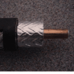
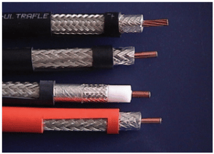
The construction of our basic cable consists of a copper or copper-clad aluminum center conductor, which is coated with an adhesive, over which a closed- cell polyethylene foam dielectric is extruded. The dielectric, in turn, is completely wrapped by an aluminum-mylar-aluminum composite outer conductor tape that is glued to the dielectric in a cigarette wrap fashion and covered by a round-wire braid. A heavy-wall polyethylene jacket is extruded over the braid. This standard construction will meet the requirements of the vast majority of applications. There are other cable constructions, which may be used with the same standard connectors and optimized for specific requirements or applications.
- If you need to snake the cable around objects to make the connection, there is flexible cable,
which utilizes a stranded center conductor and a TPR jacket for greater flexibility. This is for
situations where you need flexibility but not for continuing movement.
- Local building codes will require fire-retardant cable in elevator shafts and other vertical runs. You will need a “Riser”-rated jacket in place of the polyethylene to meet all UL and CSA building requirements, except installation in plenums. The Riser-rated jacket will not propagate a flame outside the actual area of the fire.
- For horizontal paths within a building that are a part of the air handling system, you must use a cable that is designated “Plenum”-rated by the National Electric Code. There are both corrugated and taped Teflon versions of Plenum cable with the taped Teflon being much more rugged and resistant to kinking. Plenum-rated cables will have low toxicity if subjected to fire.
- A cable that often meets a need in the wireless data field is identical to the standard construction except for the outer conductor. The outer conductor is composed of a flat silver plated copper flat braid that is covered by a spirally wrapped aluminum composite tape that is covered by a high-coverage, tinned copper round-wire braid. This cable is designed for applications that will see continued flexing, such as the portable point-to-point microwave antenna setups used by television news-gathering teams.

There are a few other cables that may be of interest. For example, if you need to run along the outside of residential structures or along the ceilings of offices, use a white-jacketed product. Also available are PVC- or TPR-jacketed versions of the standard construction, which allow for incrementally more flexibility without adding to insertion loss and finally an FEP-jacketed version of the plenum cable that provides a low-loss, high temperature cable.
Selecting the right connector
The overall performance and reliability of the transmission line is going to be affected by the percentage of the incident signal that is reflected back along the length of the transmission line. Certainly, the impedance uniformity and overall cable quality are important, but the quality of the connectors also plays a big role that is often overlooked.

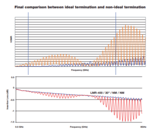
VSWR (signal loss) may be attributed to reflections due to impedance and mismatches within the connectors. The ratio of reflected signal will increase with an increase in frequency. At a certain frequency, a mismatch loss attributed to the higher VSWR will create a noticeable divergence in insertion loss curves (see above chart). It’s conceivable that a short jumper assembly can actually have more than twice the theoretical insertion loss through the use of inferior connectors or connectors that are not properly compensated for higher frequencies.
Proper termination of the cable
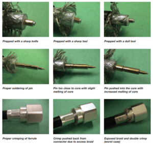
The preparation of the cable can greatly affect the overall performance of the assembly or jumper. The length of the various strip-backs from the end of the cable should be in accordance with the manufacturer’s recommendations. In addition, care must be taken to cut the dielectric and outer conductor square and to cut it with a sharp instrument so as not to form an indentation in, or deforming of, the dielectric or produce a jagged outer conductor. Commercially available cable-stripping tools are great in assisting with obtaining the proper strip length as well as assuring a square cut of the dielectric. Make sure that the tool is sharp.
The soldering of the pin is another step in the termination process that can have a great impact on the final performance of the transmission line. Aside from cold solder joints and the risk of opens, the pitfalls that are present during the pin soldering process are (1) excess solder and flux, (2) improper pin to core gap, (3) melting of the dielectric and (4) the actual pushing of the solder cup of the pin into the dielectric material. All of the items that were just mentioned will create impedance mismatches that will decrease the efficiency of the transmission line by increasing the signal reflections within the assembly. This decreased efficiency will be represented by higher VSWR levels.

The jacket strip-back and crimping of the connector is also an important step in more ways than one. The first thing that comes to mind is the mechanical integrity of the interface and the pull strength of the connector. It is important that the jacket is removed without nicking the braids. A slight knick in the braid, which may be barely visible, will greatly weaken the termination strength of the connector. Again, the best way to accomplish this is with a custom strip tool. Optimal termination strength will never be achieved when using a knife to strip the jacket, regardless of how skilled the installer may think he is. Once the jacket is removed, the braid should be left woven with just the end of the braid flared away from the core. This will assure maximum torsional strength. Last, from a mechanical standpoint, the ferrule must be crimped with the proper crimp die.
The crimping of the connector can also have ramifications from an electrical standpoint. The ferrule must be crimped as close to the connector as possible. To do this, the excess braid should be cut off so that no braid protrudes when the ferrule is pushed up against the connector. The crimp die must then be pushed up against the back of the connector so that the crimped ferrule does not compress the jacket in any way. You can probably visualize how sloppiness at this stage of the termination process can impact the electrical performance of the cable assembly. If the jacket is compressed, it has nowhere to go but to compress the foam dielectric and create a section of low impedance.

This chart demonstrates how easily the performance of the transmission line can deviate from the optimal. We are using high quality cable and connectors in this demonstration and that the degradation of performance portrayed by the red curve is strictly due to errors in termination. This demonstration is not an exaggeration. I can tell you that these errors are commonplace.
Minimize the Variables in the Field
Using a spring-finger or “EZ” connector in the field is a good means of minimizing the variables that will affect performance. They employ a gold-plated, Beryllium copper center pin. Using these connectors in concert with a sharp strip tool, a simple de-burr tool and the proper crimp die can make the termination process almost fool- proof.
When possible, such as in the case of cable assemblies that are of standard length and or configuration, it is wise to purchase pre-terminated assemblies from quality manufacturers, which are factory tested for VSWR and insertion loss across the frequency band of the application.
Deploying Cable in the Field
The cable should always be handled, formed and secured, keeping in mind that the cable diameter must be maintained throughout its entire length. Before even starting an installation, the cable should be examined for damage. Be especially observant of the outer layer of cable on a reel to ensure that it hasn’t been damaged during shipping. When purchasing ready-made assemblies, be on the lookout for assemblies that are captivated by tight machine-applied cable ties. These ties can distort the impedance at regular intervals and create considerable VSWR spikes at a given frequency for long assemblies.
Bending
Be aware of the minimum bend radius of the cable and never exceed this value. When approaching the minimum bend radius, a bend mandrel should be used to provide a uniform bend. Something as simple as a can should do the trick. Also, never bend the cable directly behind the connector. All the work up to this point –– such as using good quality cable, good quality connectors and closely controlling the termination variables — amount to nothing if tight bends are
made directly behind the connector and the impedance is distorted at this point.
Paying Out the Cable
Care should be taken to prevent kinking while paying out the cable. This can easily be accomplished with two people. If you must pay out the cable by yourself, suspend the coil vertically (through a pipe or drum). This will eliminate the type of kinking that is consistent with dragging a garden hose across the backyard.
Placement and Support of the Cable
Avoid running the cable across the surface of an open rooftop or along the ground out in the open where it may be trampled, driven over or have objects piled on top of it. When the traverse of an open area along a rooftop or the ground is necessary, use a trough. You can purchase a commercially available metal trough or build one using pressure treated lumber.
When running the cable between two points, suspended from the ground, always run a guy wire! Use UV resistant cable ties to sup- port the cable every three feet along the length of the guy wire. The ties should be snug but not over tight. The cable should be run at a height that will allow people to pass under it unhindered and discourage the hanging of clothes, etc., from it.
Conclusion
These are just a couple of guidelines to help with obtaining the optimal installation to ensure that your communication signals move unimpeded through your radio system. Remember, the little extra effort in planning, workmanship and training that is put forth at this point will pay dividends in system reliability for years to come.
Subscribe to our newsletter!
Interested in receiving email newsletters and other updates from Times? Subscribe now!
