Cables & Connectors Supplement
CONNECTOR TORQUE REQUIREMENTS
TED PREMA
Originally published in Microwave Journal
Times Microwave Systems
Wallingford, CT
In the world of RF coaxial threaded connections, too often the efforts of selecting a suitable connector interface, procuring it from a reliable source and manufacturing a high quality assembly are done in vain because the connector has not been tightened to the proper torque value and/or steps were not taken to insure that the connection will be maintained during its application. It is not fair to blame the installer, as sifting through the maze of commercial, military and supplier specific standards can be a daunting task.
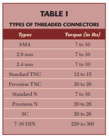
The job of a coaxial cable assembly is to transmit the RF signal with as little loss and distortion of the input signal as possible. At low frequencies, the RF connection can be quite forgiving. Anyone who has installed RF connectors for his cable TV has probably seen little degradation to the signal, provided the connection was not open or shorted out. However, as operating frequencies rise above 2 GHz, the quality of the connection becomes increasingly important. The key attribute in creating and maintaining good RF connections is making sure the connector interfaces are fully engaged during the installation and remain so during use. A critical component in this connection is assuring that the connectors are properly mated. This requires knowledge of the installation torque requirements, using torque wrenches calibrated to the proper value for installation and having a method for securing the connectors that assures that they will not become loose. The recommended torque level for threaded coaxial connectors is determined by the size of the connector and the materials from which it is made. As one would expect, smaller connectors have lower torque requirements as well as connectors made of softer materials such as brass rather than stainless steel. The application of insufficient torque will result in a poor or unstable connection while an over torque will damage the mating surfaces and coupling mechanisms. Table 1 summarizes the requirements for some of the common types of connectors.

Small diameter connectors, which include the SMA, 2.9 and 2.4 mm types, are used in the highest frequency applications. They are almost always made of stainless steel and rely on surface mating. Mid-size connectors, which include the types N and TNC, are available in more variations to address specific needs. Standard TNC and N connectors are designed for use below 11 GHz and are made of brass, which limits the installation torque that can be applied without damaging the interface and coupling components. Precision stainless steel TNC connectors have been developed to provide reliable connections under extreme conditions and to extend the effective operating frequency range to 18 GHz. The requirements for these connectors are addressed in the MIL-T-81490 and MIL-C- 87104 specifications. The installation torque level for precision connectors is increased from the standard connector value of 10 to 13 inch-pounds to 20 to 26 inch pounds. This added torque makes them more suitable for airframe and other high vibration applications.
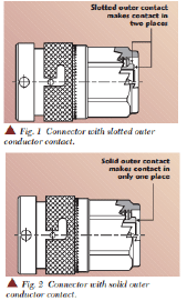
RF connections require intimate contact of both the inner and outer conductors. The center contacts on all standard connectors rely on one side, normally the female (jack) having a formed spring finger contact into which the male contact is inserted, thus assuring electrical contact. TNC and N connectors are available with either solid or slotted outer conductor contacts. Slotted outer contacts are formed and act as springs, designed to make contact with the base and side walls of the mating connectors, as shown in Figure 1.

In contrast, solid outer contacts only make contact at the base of the mating connector (see Figure 2) and although they provide excellent electrical performance and are less costly to produce, they can suffer from severe signal degradation should they become loose during use. Slotted outer contacts are therefore strongly recommended for all applications subject to vibrations. Large connectors are designed to be installed with high torque levels, thus assuring a secure connection under all conditions. The 7-16 DIN is a connector widely used in the telecommunications industry, particularly where low passive intermodulation or high power handling is required. It is designed to be installed with a torque of 220 to 300 inch-pounds, which is a full order of magnitude greater than for the type N or TNC.
Large connectors are designed to be installed with high torque levels, thus assuring a secure connection under all conditions. The 7-16 DIN is a connector widely used in the telecommunications industry, particularly where low passive intermodulation or high-power handling is required. It is designed to be installed with a torque of 220 to 300 inch-pounds, which is a full order of magnitude greater than for the type N or TNC.
MAINTAINING MATING TORQUE
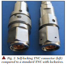
Mated connectors can come loose from vibration if not locked in some fashion. The old and tried method of accomplishing this in airborne applications is by lock-wiring the connector to its mate. The downside of this method is that it is time consuming and the pieces of wire that may be left in the aircraft during the process of installation or removal can damage critical aircraft components. Nearly all modern aircraft have adopted self-locking connectors as the standard for RF interconnects.

An example of a TNC selflocking connector next to a traditional lock-wire connector is shown in Figure 3. In this design, the TNC coupling nut is torqued to its required value of 20 to 26 inch-pounds after which the locking mechanism is engaged to prevent the coupling nut from backing off. As a further enhancement, connectors that have self-limiting torque mechanisms can be provided but at a cost of weight and size.
ALTERNATIVES TO THREADED CONNECTORS
There has been an increased interest over the last several years for alternate approaches to threaded RF connections. This interest is being driven by the desire to increase packaging
density, reduce weight, decrease maintenance time and improve reliability. Single high frequency RF connections are increasingly being done with bayonet style couplings. The most commonly known types of bayonet mount connectors are the C and BNC, which have been used for many years, primarily for low frequency interconnects. The main problem to be overcome with bayonet designs is that the surface- to-surface mating of the outer contacts relies on the spring force exerted by the coupling mechanism. For low frequency, non-phase critical applications, a slight disengagement of the interface will not adversely affect the electrical performance, when external forces pull on them. However, as the frequency increases, the instability of bayonet designs can be a major concern. This problem has been addressed with higher performance bayonet designs such as the TMA that combine precision interfaces with higher force coupling mechanisms.
MULTIPORT CONNECTIONS
Connections utilizing multiple contacts can be used to make reliable connections over a wide range of frequencies. The advantage of these connection systems is that the individual contacts are spring loaded and installed into an overall connector that is not torque sensitive. As with threaded and bayonet mount connectors, it is important that the RF plane of the two mating contacts remain securely engaged under all conditions.

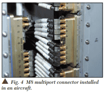
Multiport connectors are available in a wide range of sizes and styles. These include styles from the very small contacts that fit the size 12 and size 8 cavities of MIL-C-38999 connectors, M8 connectors that have equivalent performance to precision TNC, to size 1 contacts for ARINC connectors that have the same interface as type C and SC connectors. An example of an M8 multiport connector installed on an aircraft is shown in Figure 4.
Subscribe to our newsletter!
Interested in receiving email newsletters and other updates from Times? Subscribe now!
