Category Archives: Articles

Key Considerations for Coaxial Cables in Space
Key Considerations for Coaxial Cables in Space
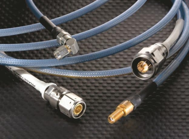
Phase Stability
For phase-sensitive systems, compensating for the knee multiple times per orbit as the spacecraft moves through its operating temperature range is challenging and limits overall system performance. Other dielectrics such as Times Microwave’s TF4® dielectric and Sio2™ silicon dioxide materials do not produce a similar non-linear change. In addition to controlling overall phase change vs. temperature, designers may need to characterize the hysteresis of the phase change across the operating temperature range. The silicon dioxide dielectric provides linear phase change with exceptional repeatability for applications requiring low hysteresis.
Return Loss
The second major environmental consideration for spaceflight applications is electrical performance over radiation exposure. Plastics such as PTFE and TF4 will degrade over time, increasing loss. For short-duration or risk-permissive missions, these long-term concerns may not be compelling. For long-duration, high-exposure, or high-reliability missions, using radiation-tolerant coaxial solutions such as the SiO2 line is better than shielding a plastic.
High Density
The high-frequency cables required for spaceflight applications have a shorter range, requiring a dense network of antennas.
Many different requirements may apply in terms of RF and microwave interconnects used with ground-based satellite dishes, such as high-frequency performance, low-attenuation needs, phase stability, and low-PIM performance. Our TCOM®, MaxGain®, and LMR® products are designed to address these needs.
At the same time, technology providers are working on advanced designs that accommodate extremely restricted space constraints and producing spaceflight connectors that successfully operate up to 70 GHz. Our new InstaBend® high-performance microwave assemblies provide a flexible preassembled design for interconnects between RF circuit cards, modules, and enclosure panels, enabling space-efficient implementation for higher frequencies.
The high-performance microwave assemblies are ideal for in-the-box applications because the cable can be bent very closely behind the connector. This minimizes footprint, saves room, and simplifies cable routing, eliminating the need to protect the back of the connector.
Materials
In addition to the issues of smaller cables tightly packed and connected, space applications require materials and constructions that withstand radiation, sandblast storms, extreme temperatures, and pressure variations. The latest materials technology and manufacturing processes are needed.
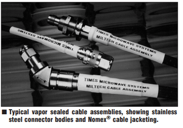
In the past, semi-rigid cables have been the standard cabling solution in space applications because their solid copper outer conductor protects the dielectric material inside. Today, special semi-rigid cable solutions based on silicon dioxide dielectrics are available. For example, our SiO2 cable assemblies are highly temperature and radiation resistant.
Some antennas fold into the satellite when not in use and unfold upon arrival at the satellite’s destination. There, the antennas will point to other satellites, get a position, and lock mechanically. Flexible cables are needed to work around the elbow that enables the antenna to fold and unfold.
Connectors
New styles of connector interfaces such as Times Microwave’s TLMP address the electrical and mechanical weaknesses of traditional high-frequency SMP/SMPM interfaces for high-vibration spaceflight applications. They visually indicate full engagement by exposing a green ring on the connector body when successfully mated.
Once routed correctly, it is also critical to ensure that the cable is appropriately mated to ensure effective RF performance. For threaded connectors, RF assembly suppliers should be able to provide recommended connector torque values. Designers should also consider multiport connectors that will mate multiple contacts simultaneously, reducing the opportunities for error.
Times Microwave Systems®: The Ideal RF Interconnect Partner for Demanding Space Applications
Qualifications and Heritage
Our team has deep experience in space and other mission-critical industries such as military and defense.
Breadth of Products
Components deployed in space must meet many technical standards. There is, however, no standard for how to apply these materials to construct a consistently reliable RF solution. That is where our expertise and access to a full range of product options are needed. You can select the suitable material and choose from multiple cable constructions, various connector designs, and assembly techniques, all from the same supplier.
Dedicated Technical Experts
The complexity of space applications requires an effective partner who will work collaboratively to extend your design team. We help our partners understand the electrical and mechanical trade-offs particular to their unique space applications. Our technical team asks the right questions and listens to understand your unique needs, always considering innovative solutions.
Achieving High Density in Mission-Critical Circuits
Achieving High Density in Mission-Critical Circuits
By David Kiesling
Originally published in Microwave Journal
Technology providers are creating advanced new wireless system designs within restricted space constraints in avionics, 5G, space and many other industries. These applications rely on high density RF interconnections capable of high signal integrity and reliability in ever more miniature housings. There are many challenges to providing practical RF interconnections in such dense housing environments. Fortunately, innovations in RF interconnections have led to reliable, high performance solutions that can fit the tightest spaces available, even at the most difficult interconnection angles.
AVIONICS
Avionics applications have limited space as they accommodate more application needs throughout the airframe. In the past, it may have been common to have 12 antennas on an aircraft, but there are now 50—even hundreds in some cases—antennas serving advanced avionics systems. More antennas in aircraft environments leads to more signal paths and the need for more RF interconnect solutions to accommodate them.
5G
As more users rely on 5G services, more antennas will be needed to provide coverage, both at lower FR1 frequencies (under 6 GHz) and at higher FR2 mmWave frequencies. Antenna densification is required to deliver increased peak data speeds, ultra-low latency, enhanced reliability, enormous network capacity and increased availability for 5G. Many 5G networks employ MIMO antennas, which are shrinking in size as higher frequency bands are used to accommodate larger bandwidth requirements. This translates into more antennas in smaller spaces and more RF interconnections within those smaller spaces.
5G small cells, such as micro, pico and femto cells, are examples of the electronic densification within 5G networks as they are spaced much closer than traditional wireless macrocell towers, often only 100 yards apart. Demand for high density cabling solutions to accommodate the necessary
connections in smaller, more compact installations will continue to grow.
SPACE
Equipment used to support space technology must be lightweight, compact, reliable and capable of withstanding high levels of shock, vibration and radiation, as well as wide temperature ranges. RF coaxial cable assemblies must be designed to perform reliably in the smallest possible footprint. The high frequency cables required for space applications must support low loss communications, requiring a dense network of antennas.
HIGH DENSITY INNOVATIONS ABOUND
High density RF interconnection solutions have evolved from individual assemblies with multiple coaxial connectors to a single connection port. There are a wide variety of unique high density options suited to fit the specific needs of an industry/application, including multiport and mini-multiport connectors, bundled cable assemblies, locking miniature blind mate connectors and cable assemblies for densely packed in-the-box applications. Common requirements for these environments include ease of installation, high vibration (cannot come apart) and environmental seals.
MULTIPORT AND MINI-MULTIPORT CONNECTORS
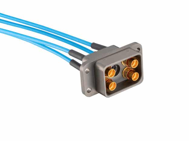
Multiport and mini-multiport connector solutions are ideal for high density avionics environments, where space is at a premium, accessibility for maintenance is limited and performance is mission-critical. These connectors consist of multiple coaxial contacts of the same interface integrated
into a single connector module or shell. There are numerous options for these types of connectors, including those with reduced size and weight that provide excellent electromagnetic shielding and phase stability with low VSWR and insertion loss to 20 GHz for multiport connectors and to 40
GHz for mini-multiport connectors. See Figure 1 and 2 for examples.
BUNDLED CABLE SOLUTIONS
Densification creates numerous challenges related to installation, torquing, ensuring proper weather sealing and more. In addition, an increasing number of technologies such as 5G small cells have limited space for equipment, so minimizing size and weight are also key goals.
With so many components in such a small space, maintenance can be challenging. If an interconnect fails, it can be hard to troubleshoot the exact one. Moreover, installation can be a time-consuming, labor-intensive and logistical nightmare. Hooking up the right cables, ports and torquing can be difficult when working with multiple connections. Proper weather sealing is also necessary; it is imperative to ensure that the seal is secure but not over-torqued.
A bundled cable solution can help create the perfect flexible antenna jumper for applications requiring multiple runs, such as 5G. A spiral configuration of multiple flexible and ultra-flexible jumper cables can be created under a common polyurethane outer jacket to promote easy installation and
improved operation. The individual coaxial cable runs are spun together in a way that easily flexes, essentially creating a bundle, which is then run through a large jacket extruder where a ripcord is placed.
This design enables four or five individual cables to be fed into the back of an industry standard MQ4/MQ5 bundled connector, incorporating multiple RF ports and significantly reducing the number of cables that have to be hooked up. MQ4/MQ5 bundled solutions also save a lot of labor and enable
a more rugged solution. They also make the assembly more weatherproof and UV resistant.
Using the four- or five-conductor solution eliminates the need to create individual weather seals, resulting in tremendous labor savings. Furthermore, it reduces the need to worry about coupling torque, which is critical because all it takes is an error on just one weather seal to create a point of
ingress for water that could create a multitude of problems and even potentially shut the system down. With a bundled solution, the connection between the male and female cluster connectors is sealed to IP-67, as are the connector bodies and the transition from the cluster connector to the bundled cable. Any potential system troubleshooting becomes much easier. Finally, the possibility of hooking up the wrong cable to the wrong port is eliminated. The solution is keyed, so the cables can only be hooked up a certain way—no torque wrenches, know-how or special technique required.
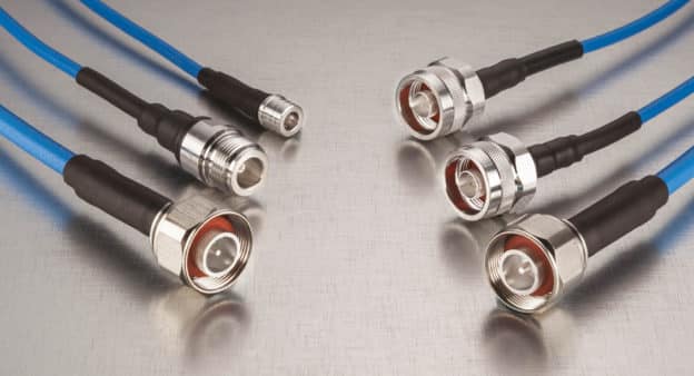
Bundled solutions are optimal for high density challenges as they permit installation in tight spaces; instead of connecting multiple threaded connectors, just one will do the job. They are faster and easier to install and maintain and provide one firm, reliable connection to support consistent high performance. Their design has many use cases, thus becoming particularly popular in applications
where cable installations and rising operating frequencies demand coaxial cables and connectors to deliver high signal integrity and reliability. An example of this type of solution is the TMQ4 and TMQ5 bundled cable assemblies from Times Microwave Systems® shown in Figure 3.
LOCKING MINIATURE BLIND MATES
A new generation of locking miniature blind mate connectors (TLMB) is specifically designed to overcome performance issues arising from typical SMP connectors’ susceptibility to electromagnetic interference (EMI) and electromagnetic compatibility (EMC) interference, liquid and salt ingress. Their rugged, sealed design is more durable to withstand harsh conditions and operate in severe environments. TLMB connectors retain the small form factor of the SMP for highly dense environments but add improved environmental, shielding and power capabilities, with a frequency
range from DC to 60 GHz.
While SMPs are still a valuable connector option for many designs, they pose problems as applications demand higher and higher frequencies. One of the critical issues is shielding and EMI.
Similarly, the SMP’s design reduces its ability to function without affecting other equipment in the same environment. The connector’s signal leakage issues often result in failed EMC tests. In short,
the SMP’s lack of proper electrical bonding and shielding exposes the conductor’s signal to external influence.
This signal leakage limits how closely the connectors can be placed in a single shell; without proper shielding, the contacts must be kept at a greater distance to prevent signal interference. With the improved shielding of a TLMB, more connectors and cables can be added in a much smaller footprint without interference issues.
Another major failure area in the SMP’s design makes them susceptible to ingress from saltwater, fuel and other contaminants. The lack of an environmental seal due to their mechanical openings makes SMPs prone to corrosion and failure. Another problem arises with using SMPs in high vibration applications, where their easy connect/ disconnect design makes them susceptible to unwanted de-mating in high vibration environments. TLMBs were created for high-reliability, high vibration environments such as military and aerospace. Areas where EMI may be an issue, such as
shipboard or aircraft, need an environmentally sealed and shielded connector.
The standard SMP may also disconnect in high vibration environments such as a carrier landing, weapons launch or any powerful weapons platform, making a locking miniature blind mate connector the ideal choice.
CABLE ASSEMBLIES FOR DENSELY PACKED IN-THE-BOX APPLICATIONS
Additionally, it may be optimal in high density applications to reduce the footprint required behind the connector to help install numerous cables into a very small space. Minimizing space between the cables and connectors is also necessary for the interconnect system to survive the high vibration and other harsh environmental conditions found in applications such as space and avionics.
New cable assemblies can be bent around tight corners and very closely behind the connector to minimize footprint, save space and simplify cable routing in tight spaces while offering low loss and optimized performance. Originally designed for space flight applications, this type of high performance assembly uses a compact, phase stable, highly flexible, micro becoming axial cable that can easily accommodate densely packed in-the-box applications. For example, Times Microwave System’s new InstaBend® high performance microwave assemblies provide a flexible
preassembled design for interconnects between RF circuit cards, modules and enclosure panels. InstaBend is ideal for in-the-box applications with space constraints, including space flight, thermal vacuum, microwave test and other commercial and military applications. The cable can be bent very closely behind the connector, minimizing footprint, saving space and simplifying cable routing (see Figure 4). This also eliminates the need to protect the back of the connector.
Additionally, InstaBend provides these benefits at a dramatically reduced lead time compared to competing solutions. The high performance microwave assemblies are available in standard configurations or customized to meet an application’s specific needs. This new product’s ability to bend from connector to connector provides maximum flexibility and minimum use of available volume in high density, inside-the-box applications.
SUMMARY
As advanced new mission-critical technologies are introduced, RF interconnect requirements are changing drastically, including the need for novel solutions to accommodate extremely restricted space constraints and rising operating frequencies. New innovations in high density RF interconnects are emerging to deliver high signal integrity and reliability in increasingly dense environments.
When selecting the right high density RF cables and connectors, it is best to work with a partner whose engineers can identify the application’s unique needs and design an optimized, easier to use solution—creating better electrical, mechanical and environmental performance. Look for a supplier
with a long history of building quality cable and connectors, along with the skill, processes, techniques and materials to bring custom solutions for specific application needs to life
RF Interconnects for 5G Infrastructure and Applications
Pin Height
Phase Track Cable – TF4 Dielectric: The “Knee Replacement”
Optimizing Microwave Signal Transmissions In Extreme Cryogenic Environments
OPTIMIZING AN RF TRANSMISSION LINE
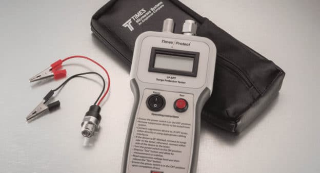
On Site Testing of Lightning Protection Devices
New Connector Field Installations Improve System Reliability
Connector Installation
New Connector Field Installations Improve System Reliability
By Kevin Moyher
Here is a short case history demonstrating a solution for reliable field-installed connectors use in high reliability wireless E911 systems
Across the country, CDMA, TDMA and GSM wireless communication sites are being upgraded to meet the requirements of the FCC’s Enhanced 911, or E911, mandate. Phase II of this ruling requires that network-based wireless location systems locate a wireless phone user to within 100 meters 67 percent of the time, and to within 300 meters 95 percent of the time. The quality and reliability of these systems is paramount; people’s lives may depend on it. Applications for this system are personal security, medical alerts, child tracking and accident response.
An Example of E911 Equipment
True Position is a leading supplier of the complex equipment that is integrated into cellular and PCS base stations to give them user location capability. True Position utilizes UTDOA (Uplink Time Difference of Arrival) technology to locate a subscriber’s cell phone. The LMU (Location Measurement Unit) is installed at each cell site. This equipment passively overlays the existing wireless network, sending critical data back to the operator’s Mobile Switching Centers where LCs (Location Calculators) perform the multipath mitigation algorithms. When a wireless phone user whose carrier employs True Position’s equipment dials 911 and activates the E911 network, the equipment in the area surrounding the caller is activated and begins to perform the complex calculations necessary to pinpoint the caller.
The reliability of this equipment is critical, and it has been optimized and ruggedized to perform with high reliability. However, there are only so many safeguards and safety measures that can be incorporated into the components themselves. The ultimate reliability of this system depends on the quality of the interconnecting cable runs. As shown in the photos of Figure 1, the E911 hardware has to be connected to each of the transmit and receive antenna runs, requiring multiple short interconnect cables. These cables are built from small core low-loss, flexible 50 ohm coaxial cable. True Position minimized some of the installation variables by using the QMA interface for these interconnecting runs. This interface can best be described as a high performance, quick connect SMA. The adoption of this interface eliminates the need for threading of small coupling nuts and the concern for achieving the proper mating torque.
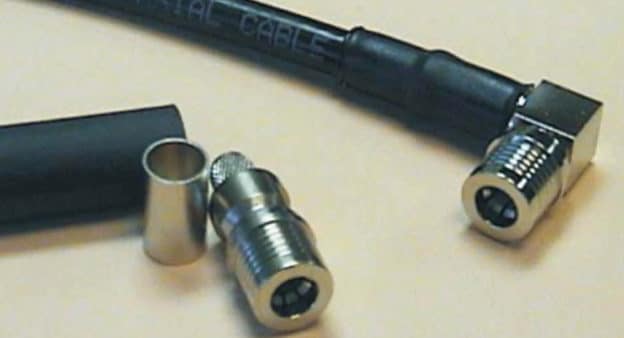
Times Microwave has contributed to high performance and reliability of these systems, starting with the basic requirements of high-quality cable and connectors with very good return loss. However, since the layout of every base station is different and the lengths of the interconnect cables vary accordingly, the cables must be cut and terminated in the field. This reality prompted the design of a series of EZ (spring finger center con- tact) connectors that interface with Times’ LMR®-240 cable (Figure 2). Though QMAs are the dominant interface in the system, SMA and Type N connectors are also widely used. These EZ connectors eliminate the need for soldering in the field and solve the issues of pin height and pin to core gap. These three variables are often the largest contributors to inconsistency in the performance of field terminated interconnect cables.
The right angle EZs employ a unique design. Many spring finger right angle connectors have a 90° swept center pin with a mitered outer conductor. This design offers ease of termination at the expense of return loss. Times has taken the typical soldered right angle design and improved upon it. The straight brass center pin has been replaced by a straight beryllium copper pin that is bifurcated at the back end with a lead-in for the cable center conductor. This configuration has the ability to fine tune the impedance across the right angle. Where typical EZ right angles have a return loss weakness over a properly designed right angle solder connector, this new design actually has an advantage: excess solder build-up is no longer an issue. Going a step further with this design, a stop is placed inside the connector so that the pin can not be over extended beyond the center pin.
Optimization of the field terminated cables goes beyond connector design and includes the development of two easy-to-use termination tools. The first of these is a “one-step” cable stripping tool (ST-240EZ). Many small coaxial cable prepping tools are generic tools which are completely adjustable. These tools are capable of being adjusted to work with different cables but can be a real minefield in terms of potential termination problems (i.e., nicked outer braids, nicked center conductor, crushed core, improper strip lengths, etc.). The ST- 240 is a completely customized tool. The cable slides into a cable slot until it hits a stop. The blade package, containing two hardened alloy blades, is then released onto the cable, the index finger is placed through the loop at the end of the tools handle and the tool is spun clockwise around the cable for three to four full revolutions. The tool is then grasped as close to the cable as possible and pulled away from the cable, exposing the center conductor and tinned copper round wire braid.
This tool assures that the cable is stripped to the proper dimensions every time. It preps the core square and clean without crushing it or rip- ping the outer conductor and it preps the center conductor clean without nicking. The most important function which the tool performs is to expose the braid without nicking it. This is a very important requirement in the termination process that often gets overlooked. The braids on these small core flexible cables are of a very small diameter and a slight miscalculation with the pressure applied to a knife or a slight mis-adjustment of a variable stripping tool could effectively wipe out half or more of the braid, resulting in poor connector retention. The introduction of these EZ connectors for LMR-240, and the simple tools to assist with their termination, has created a nearly foolproof choice for the field assembly of short low-loss interconnect cables.
Microwave and RF Cable Assemblies: The Neglected System Component Part 2
Microwave and RF Cable Assemblies: The Neglected System Component Part 1
Making the Connection…With Coaxial Cable
Interpretation of Electrical Test Data with Regards to Microwave Cable Assemblies
How To Choose the Best Test Cable
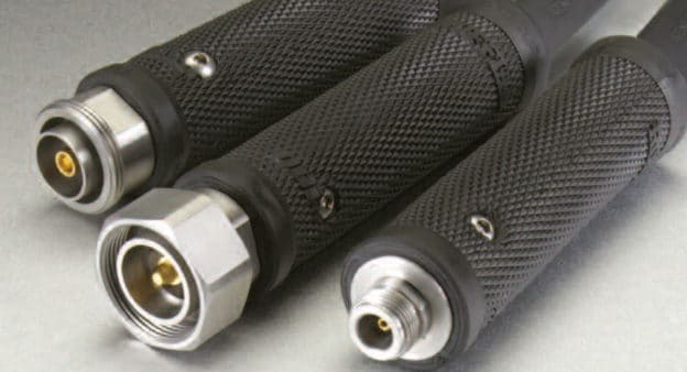
A NOVEL SUPER-ROBUST HANDGRIP FOR COAXIAL CONNECTOR ASSEMBLIES
Don’t Overlook the RF Connector
Broadband Wireless
Don’t Overlook the RF Connector
Technical Primer: Using the Proper Connectors Can Be Critical in High-Frequency Applications
By Kevin Moyher
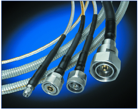
Connectors on an RF assembly are often taken for granted. In many cases the designer is satisfied if he has found a connector of the proper interface that will physically fit onto the cable that he intends to use. Impedance uniformity across a cable assembly is paramount in the efficient transmission of RF energy. The cable assembly is basically only as good as its weakest link. The time and money spent on high-quality, low-loss cable can be wasted if there are large impedance mismatches within the connectors, at the connector-cable interface and at the connector-device interface.
The Connector and Wave Reflection
Ideally, the RF connector will have a uniform impedance across its entire electrical path and a VSWR (voltage standing wave ratio) rating of 1.00:1. The VSWR value of a connector is the expression of the percentage of the input signal that is reflected back toward the source due to mismatches within the connector. This VSWR value can also be used to express the percentage of reflections across an entire assembly.
A uniform impedance across the connector, the cable and the connector-cable interface will allow the input signal of an RF transmission line to be efficiently transmitted to the output. In this case, reflections created by impedance mismatches will be nonexistent, and the losses across the assembly length will be strictly a function of the resistance of the conductors, the electrical properties of the dielectric and the shielding of the cable.
Connectors with greater impedance mismatches will have higher VSWR values associated with them. These VSWR values can be directly correlated with a value called mismatch loss (for example, a VSWR value of 5.85 has a mismatch loss of 3.021 dB).
The overall insertion loss for an assembly can be determined by calculating the theoretical
attenuation of the assembly and then adding all of the mismatch losses that would be associated with the assembly (i.e. cable, forward connector and aft connector). This calculated value represents a worst-case scenario. It would become reality if the peaks of the incident wave and all of the reflected waves were in phase with each other. This scenario is possible, but unlikely. However,
it is almost certain that the overall insertion loss of the assembly will increase as the reflections caused by mismatches along its length increase.
A perfect connector with a 1.00:1 VSWR is not possible, or I should say, it is not economically
viable. There are line-size transitions that are taking place within the connector. There are many variables involved in optimizing these line-size transitions. An abrupt transition may work well at lower frequencies, but this transition must be compensated when working at higher frequencies.
This is not an exact science. However, experienced connector designers can use time domain reflectometry to map the impedance mismatches across the connector. They can then improve the uniformity of the impedance across the connector. The art in doing this is not simply in finding a way to properly compensate the connector but in doing it in such a way that it can be produced economically.
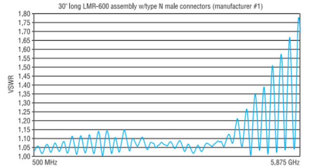
VSWR Performance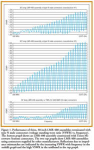
VSWR performances of three 30-inch LMR® assemblies are shown in Figures 1 and 2. The three graphs in Figure 1 display the performance of LMR-400 assemblies terminated with type N male connectors. The bottom graph of Figure 1 shows the performance of an assembly that was constructed with Times Microwave Systems’® connectors, while the top and middle graphs display the performance of assemblies constructed from connectors supplied by two other leading connector suppliers.
The first thing that comes to mind when looking at these traces in Figure 1 is that the nodes are similarly shaped and very cyclical, indicating that the cable itself has a very uniform impedance. In the event that the cable varied in impedance, the trace would look much more ragged. The VSWR trace of a cable with very poor impedance uniformity would look almost like random noise.
Based on this information and the fact that each of these 30-inch assemblies was made from the same lot of cable, we know that the steadily increasing VSWR with frequency in the middle graph of Figure 1 and the high VSWR in the midband shown in the top graph can be attributed to reflections
due to impedance mismatches within the connectors.
These three curves in Figure 1 demonstrate how the size and material transitions within a particular connector design may be compensated to perform well up to a certain frequency. It is also possible to design a connector that may perform very well in a particular band but reflect a larger percentage of the input signal at frequencies both above and below the designated band.
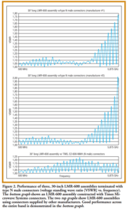 Figure 2 compares three 30-inch LMR- 600 assemblies. The assembly represented in the bottom graph of Figure 2 has been built with Times Microwave Systems’ EZ-600-
NMH connectors. The assemblies represented in the top and middle graphs of Figure 2 have been built with connectors from two other leading suppliers. The top and middle graphs indicate good performance in the low band, excellent performance at midband and very quick roll off in the high band. The assembly represented in the bottom graph of Figure 2 indicates good performance across
the entire band, with excellent performance at the high ISM (Industrial Scientific Medical) band.
Connector Design for High Frequencies
It gets increasingly difficult with connectors, as with cable, to design, build and maintain the tight process controls that are necessary to achieve a high level of performance over a broad frequency band. It’s especially difficult as the frequencies climb well beyond the 1 GHz level, such as in the
5.8-GHz ISM band. Although it is possible to optimize connectors to perform well in certain bands, it is rarely viable from an economic standpoint.
Most connectors are rated for broadband performance to a specific maximum frequency. Unfortunately, most manufacturers of commercial RF connectors have not been able to keep up with the improvements that would be necessary to obtain reasonably good performance at the 3.7- or 5.8-GHz level, never mind optimal performance.
As little as three years ago, most applications were operating below 1 GHz; as recently as two years ago, most applications for commercial cable and connectors were operating below 2 GHz. It is these cellular and PCS (personal communications service) bands for which most connectors were designed. Someone working in these bands could basically pull any connector off a shelf and it would be a pretty safe bet that the performance would at least be respectable. Most connector manufacturers were slow to understand that a connector that was sufficient in a PCS application at 2 GHz may not meet the requirements for a 2.4 GHz application in the ISM band. The proliferation of data applications in the ISM bands has placed certain demands on connector performance. These bands are unlicensed, and therefore the Federal Communications Commission has placed power limitations on transmissions in these bands. The need to be assured that there is a sufficient transmit signal — but at the same time, making sure that the transmit power never exceeds the maximum allowable power — has, in many cases, created a demand for low-loss cable assemblies that are consistent and predictable in performance.
The nature of data transmission itself has also pushed systems to reduce noise levels to their absolute minimum. The best way to do this is to minimize the power levels of the system. Hence, there’s a need for low-loss cable, and, just as importantly, low-loss assemblies. As an added challenge, some of these systems are now operating in the 5.8- GHz band.
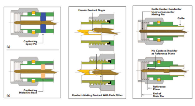
A desirable feature to have in any connector, and especially in one that must be field installed, is a captivated pin. The pin may be of a spring-finger design and permanently pressed into the dielectric or it might have a shoulder on it that will make positive contact with the bottom of a counter bore in
the connector dielectric. It’s not a stretch to imagine that the pin height of a connector with a noncaptivated pin, when installed in the field, may be 10 to 20 mils off. This error will create shifts in impedance throughout the connector, especially if there are many diameter transitions in the pin.
The Cable Design Factor
There are an enormous number of 50- ohm coaxial cable designs available. The designs encompass standard RG designations, as well as specific requirements that have arisen over the years. These designs have been devised to optimize certain parameters of the cable, such as attenuation, impedance uniformity, velocity, time delay, diameter, bend radius, flexibility, temperature range of operation and weight.
These parameters are optimized by varying center conductor, dielectric, outer conductor, and jacket materials and sizes. Optimization is also accomplished by varying the processes by which the cable is produced. Although most of these cables are 50-ohm cables, many of them present their own unique physical considerations when they are terminated with a connector.
Times Microwave Systems makes a variety of 50-ohm coaxial cables, more than any other manufacturer. The product line includes RG cables and the LMR line of low-loss flexible cable that is widely used in telecommunications and has become the accepted standard for wireless data.
The Connector-Cable Interface
There are an enormous number of connector interfaces that are in use today. However, in wireless communications more often than not, we find ourselves working with SMAs, TNCs, Ns or 7/16 DINs. The need for economic solutions in the development of wireless infrastructure requires us to use the smallest diameter cable that will keep us within our loss budget and meet any other requirements that the system will place on the cable.
Factoring in the need to work with the smallest cable available, it can be quite a task to find the ideal connector for a particular cable. Considerations include the variety of cable designs, the number of connector interfaces that are dealt with, and issues such as gender, straight or right angle, clamp or
crimp, connector material and plating. Additionally, most cable manufacturers do not design or build connectors, and most connector manufacturers do not design or build cable. Hence, a certain level of frustration can be expected. For purposes of discussion, we will assume that we are working with cable that has a uniform, 50-ohm impedance. Also, we assume that our connectors have a uniform impedance across their length (including the compensation necessary to carry out the line-size transition from the interface to the core diameter that is being considered). At this point, the most important consideration is the mechanical fit between the transfer body of the connector (the effective outer conductor) and the outer conductor or shield of the cable itself. Ideally, this interface will be smooth and mechanically intimate around the entire 360-degree circumference of the connector.
Some connectors are designed to snugly fit over the outer shield of a cable. Other connectors are designed to fit snugly over the dielectric and have the shield or outer conductor crimped or clamped to the outer surface of the transfer body of the connector. In any case, the inner diameter of the
outer conductor must be maintained as best as possible when making the cable-connector transition, and this transition must be mechanically sound. It doesn’t do any good to have an assembly that will perform reasonably well on a workbench but deteriorates quickly when exposed to real-life situations such as wind, vibration and temperature shifts.
Conclusion
As the frequencies of new applications continue to rise and performance requirements become increasingly demanding, the connector must be looked at closely. Factors include the mechanical variables that will affect overall electrical performance, performance under extreme conditions and the long-term ability to withstand the environment. Also, each connector has its own impedance characteristics similar to a fingerprint. Various connector designs will be associated with different VSWR values at a given frequency, and, in some cases, may have a significant impact on the overall insertion loss of a microwave assembly.
About the Author:
Kevin Moyher is a sales engineer at Times Microwave Systems. Times Microwave Systems is a division of Smith Industries PLC and has been involved in the design and manufacture of high performance coaxial cables for more than 50 years.