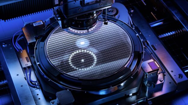
Wafer Fab Equipment
Leave a reply


Maria Calia, Director – Space and Missiles
Times Microwave Systems
Originally published with Connector Supplier
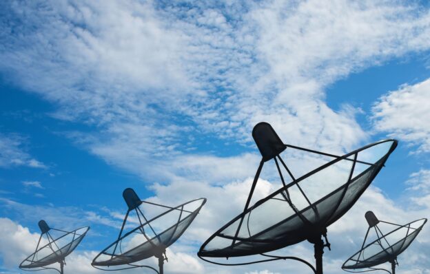
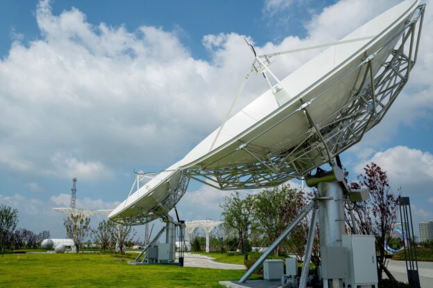
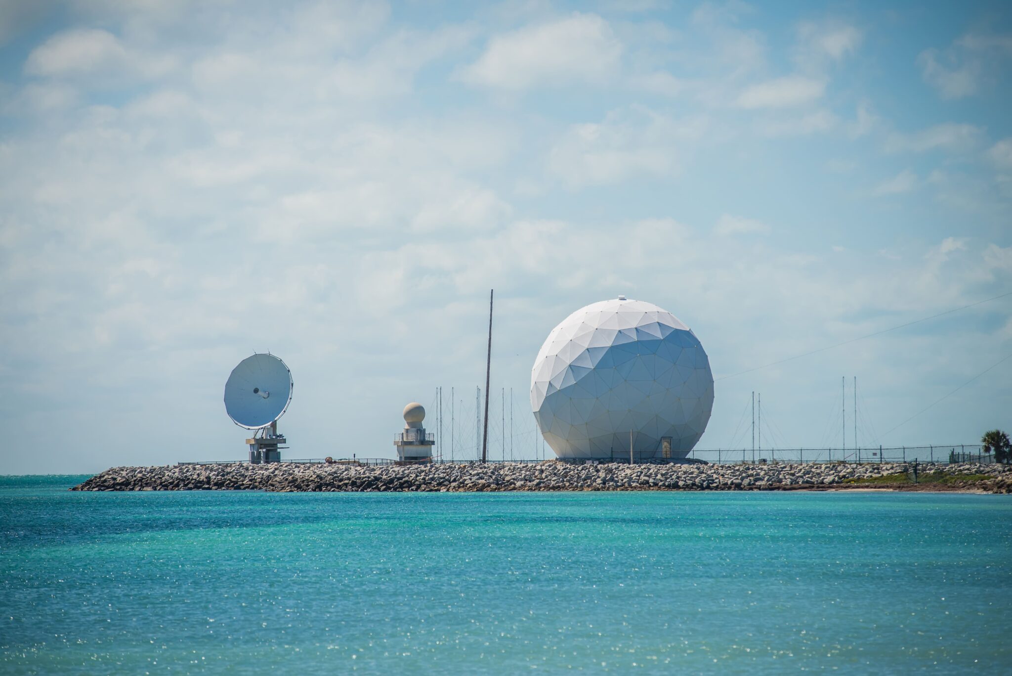
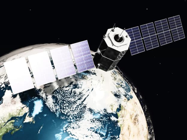
The commercial space industry is going through exponential growth, fueled in part by low-earth orbit (LEO) satellite applications. LEO satellites operate at lower altitudes and travel at high speeds around the Earth, in contrast to the traditional GEO (Geostationary Orbit) satellites used by government agencies such as NASA.
Each LEO satellite completes an orbit in less than two hours and covers only a small area of the Earth’s surface at a given period of time, due to its proximity—only 500-2,000 km—to the planet. This concentrated field of view results in a shorter communication latency, making LEOs ideal for applications that require real-time data transmission and global coverage. For example, companies like Amazon (Project Kuiper) and SpaceX (Starlink) are launching thousands of LEO satellites to provide global broadband internet coverage. Thousands must be launched into orbit, one following the other, to create “constellations” that ensure consistent and comprehensive coverage.
When it comes to achieving fast, reliable communication and high-performance operations, the RF cable assemblies used in LEO satellites play a crucial role. RF interconnects act as the vital bridge between many critical systems, including payload, communications, signal transport, and processing.
However, the extreme environmental conditions of space present unique challenges. That’s why material selection is essential when choosing a coaxial cable assembly for LEO satellites. Factors including radiation resistance, shielding effectiveness, outgassing, and whiskering must be evaluated, as well as cable performance parameters such as phase stability over temperature, stability over flexure, and attenuation.
The materials used within the cable in an RF assembly significantly impact its performance. For example, cable assemblies for commercial space applications can be subjected to 30 Mrads of radiation and temperatures anywhere between -90 °C to 150 °C. Therefore, the materials used within the cable must be able to withstand extreme conditions. To ensure optimal performance, the following factors must be considered.
Radiation exposure can change the cable dielectric and degrade electrical performance. The cable location within the system determines how much radiation it will be exposed to.
Depending on construction, different cables will be rated to withstand varying amounts of radiation. System designers carefully mitigate radiation exposure within the satellite through the use of metal shields to keep components, including RF cables, below the total exposure limits. Sometimes, however, critical cables have to be routed without shielding to remote locations. For example, RF cables exiting the safety of the bus to reach a remote antenna will be exposed to increasing amounts of radiation. They must be protected or constructed using materials that will be affected less than plastic polymers.
Cables must have effective shielding to prevent electromagnetic interference (EMI). EMI is an undesirable phenomenon when an outside signal or source causes a disturbance. Without effective shielding, cable assemblies would have to be kept a greater distance apart to avoid EMI, which isn’t possible in densely packed systems like LEO satellites. Cables constructed using internal multiple shields are better at mitigating EMI.
When exposed to a vacuum environment, many non-metallic materials outgas. This includes plastics commonly used in coaxial cables, such as PTFE, FEP, and PE. Emitted gases can recondense on critical components and degrade performance. Materials used for cables and assemblies going into space must meet industry standards for low outgassing.
Tin is commonly used in solders for coaxial connector terminations. Metals such as pure tin can grow whiskers in vacuum and high-temperature environments and are generally prohibited from spaceflight use. Coaxial cable assemblies must be built with tin/lead solder alloys to avoid whiskering. For LEO applications, smaller diameter RF cable assemblies minimize the number of solder joints and are designed to fit in tight spaces.
Maintaining cable performance once an assembly is installed is necessary for the function of a LEO satellite. Three major parameters that influence cable performance include phase stability, stability over flexure, and attenuation.
Both polytetrafluorethylene (PTFE) and TF4 dielectric cables are fit for commercial space applications, but each dielectric has its place depending on the requirements of the specific use case. PTFE has a high melting point along with excellent dielectric properties, making it popular in many microwave applications. However, around 19 °C, PTFE exhibits a non-linear change in phase known as the “knee.” This phase change is problematic for applications where phase stability is crucial.
Proprietary fluorocarbon dielectrics such as TF4 can mitigate the issues PTFE presents regarding phase stability over temperature. TF4 eliminates the non-linear phase performance that occurs between 15 °C and 25 °C.
In tight or in-the-box spaces, cable flexibility is crucial for routing. However, a flexible cable needs to maintain stable performance over flexure.
The conductivity of the conductors, the diameter of the cable, and the dielectric constant are three properties that define the attenuation, or signal loss, of a coaxial cable.
High-conductivity materials, such as silver and copper, provide low attenuation per unit length but are often heavy or expensive. Lighter materials such as aluminum and stainless steel reduce overall mass but are poor conductors. Cable manufacturers frequently optimize conductor designs by cladding or plating a lightweight, low-cost base metal with higher-conductivity copper or silver for the RF path.
Larger-diameter cables provide lower attenuation per unit length than comparable smaller-diameter cables, but this comes at the cost of increased weight and a wider minimum bend radius. Larger cables cannot be bent as tightly; a tight bend will cause the cable to kink or become oblong, causing an impedance mismatch and excessive return loss.
A lower-loss dielectric generally will be lighter because it incorporates more air. More air in the dielectric materials lowers the effective dielectric constant, meaning the transmitted signal encounters less resistance or loss, making performance closer to the ideal of a wave traveling in a vacuum.
LEO satellite applications can be very different from a design perspective than their GEO counterparts. One key difference is faster development times, which means readily available cable assemblies are a must-have for rapid product development and testing. Once testing is complete, these solutions should be easily customizable to meet the unique needs of different applications.
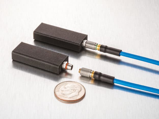
Traditional semi-rigid RF cable technology may not be suitable for smaller LEO satellites—where space constraints are significant—due to routing limitations and the need for flexibility during installation. The InstaBend® Space cable assembles are a new class of compact and flexible RF cable and connector technologies specifically designed for small satellites and similar applications. These innovative solutions can be easily routed through tight spaces without compromising performance or reliability.
These highly flexible cables can bend closely behind the connector, allowing maximum routing flexibility in small spaces like interconnects between RF circuit cards, modules, and enclosure panels. The essential advantage lies in the unique clamp technology, which eliminates the need for solder connections traditionally found in larger-diameter cable assemblies. They also offer a comprehensive solution with a triple-shield construction, broad frequency range, and exceptional durability.
A phase stable option of this type of cable assembly is also available. InstaBend PhaseStable assemblies are low-loss, ultra-flexible foam-core micro coaxial cables that eliminate the PTFE phase change around 19°C, making it ideal for applications demanding stable phase performance over temperature. This high-performance cable has the same triple-shield construction as several of our popular cables, along with a broad frequency range and strong durability. Both types of InstaBend space assemblies are designed to withstand extreme conditions in space and function continuously over a long period.
Furthermore, low-loss RF cables are crucial for LEO applications, as they can reliably maintain signal integrity over long distances. This is particularly important when transmitting high-frequency signals, as losses can degrade the signal quality, leading to errors or data loss. Low-loss RF cables also minimize power losses during signal transmission, ultimately ensuring that transmitted signals reach their destination with minimal loss in power or quality.
An example of an ultra-low-loss assembly that can meet the needs of commercial space applications is MaxGain Space assemblies, a range of high-performance coaxial cable assemblies built with a unique spiral outer conductor technology. This lightweight cable construction produces a reliable, high-frequency interconnect solution suited for applications like LEO satellites where low loss and high performance are required.
However, it is important to note that even though the design approach differs, RF assemblies used in commercial space applications are still required to meet the rigors of the environment, including the considerations outlined above. Working with a supplier with a large manufacturing footprint, extensive heritage, and access to the right materials and technologies is recommended to provide the best solution.


By Dave Slack
Originally published with Aerospace & Defense Technology
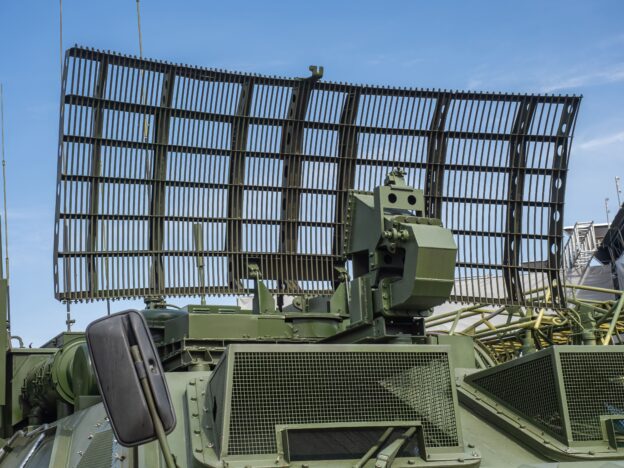
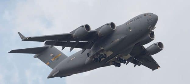
The rapid advancement of military avionics technologies is revolutionizing the capabilities of next-generation aircraft. One of the common features of modern military avionics systems is the adoption of high-frequency and millimeter-wave (mmWave) communications to achieve higher data rates and enhanced resistance to interference.
However, this introduces several evolving requirements for the RF assemblies that power them compared to the previous generation of systems that worked in lower frequency ranges. First, as military avionics systems transition to higher frequencies, RF coaxial cables, connectors, and assemblies must handle them without introducing excessive losses. Higher frequencies also require more specialized test environments due to the higher sensitivity of signals in these bands.
Following is a small sampling of applications that are changing the game for RF technologies in military avionics:
Unmanned aerial vehicles (UAVs), electric vertical takeoff and landing (eVTOL), electric standard takeoff (manned and unmanned), and other small, lightweight avionics platforms: These technologies require advanced solutions to meet new requirements while adhering to the size and weight principles that have governed their predecessors for decades. Furthermore, as technology evolves, the density of active aerial vehicles will increase, resulting in a “swarming” environment. Systems be in constant communication to avoid collisions, largely dependent upon antennas and high-frequency transceivers to enable sensors to communicate.
Hypersonic systems: New ballistic missiles, cruise missiles, manned and unmanned systems, and more are being designed to travel at Mach 5 plus speeds. These systems require low power, low loss, lightweight, small, densely packed interconnects that must withstand increasingly higher temperatures.
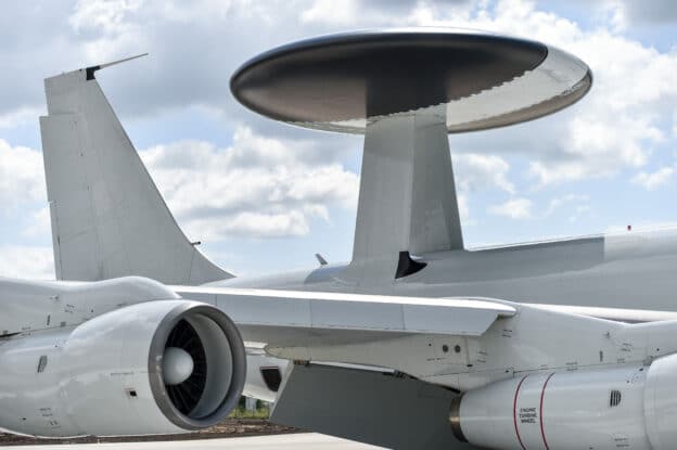
Advanced Antenna Systems: Next-generation military aircraft integrates sophisticated antenna arrays such as phased array antennas and adaptive beamforming techniques. These systems enhance radar performance, extend communication range, and improve electronic warfare capabilities. New RF technologies, such as quantum communications and terahertz communications, will push the limits of antenna systems even further in the future.
As technology rapidly advances, the challenges for RF coaxial cables, connectors, and assemblies in military avionics systems continue to grow. For example, the higher the frequency, the shorter the wavelength, which means that the components in the RF assembly must be smaller. Furthermore, avionics systems requirements demand RF coaxial cables, connectors, and assemblies that are lighter weight than ever before.
Military avionics systems also face harsh environmental conditions, including high temperatures, humidity, and vibration. RF coaxial cables, connectors, and assemblies must withstand these conditions to prevent premature failure and ensure reliable performance. In summary, avionics systems demand rugged RF interconnect solutions that can withstand demanding airborne applications while being ultra-lightweight and small yet mechanically and physically robust.
These advancements also bring forth unique new challenges for RF test and measurement.
To begin, test and measurement equipment must adapt to these higher frequencies and maintain precise calibration to ensure accurate measurements. This requires high-quality and robust hardware so the calibration doesn’t “drift” as it’s handled or goes through temperature changes or mechanical movements. As the frequency increases, small imperfections in the hardware can significantly impact the wavelength, so the hardware must maintain its calibration integrity no matter what.
As a result, precision testing is required for high-frequency applications of 18GHz all the way up to 110 GHz. The proper coaxial cable assembly is essential in this process. The RF testing process typically involves a device under test connected to a vector network analyzer (VNA), oscilloscope, or spectrum analyzer. The signal path from the instrument to the circuit board is critical, and the user must ensure the test setup does not introduce unwanted variables. This includes the test cable assembly, cable, and connectors.
There are numerous characteristics to evaluate before selecting the optimal test leads for a specific application, including test equipment type, connectors, flexibility and durability, phase stability, power, loss budget, and precision design and assembly.
Rapidly advancing technology increases test setup complexities, requiring more test leads and connection points. As a result, it’s necessary to revisit how coaxial cables and connectors are built while ensuring the latest test assemblies work with changes made by test equipment manufacturers.
Start by evaluating the type of test to be performed and what kind of equipment will be used. For example, the test could be a standard S-curve type of measurement looking at the loss of a device under test or evaluating how it performs at specific frequencies. All variables must be considered when selecting a test cable assembly that performs well for each unique testing scenario.
Connectors are a critical consideration in high-frequency applications because any inconstancy in connectors can introduce errors in the measurement that will be amplified as the test frequency range increases. The test equipment will have a specific connector type on it, usually determined by the highest frequency that the equipment can reach. For example, when testing at 110 GHz, there will be a 1-millimeter connector on the test equipment; therefore, a mating connector of the same size will be required on the test cable assembly.
Test cable assemblies must be robust enough to endure extensive handling and continuous movement from connecting and disconnecting while maintaining precise repeatability of measurement and reliable electrical performance. Many users are also interested in a cable’s flexibility and bend radius. Due to the nature of test environments, a highly flexible cable material that can be moved around on a test bench in a production or R&D environment is often essential.
Furthermore, testing often moves from module to module. High frequencies could require recalibration when a module or cable is moved. Using a coaxial cable that can bend and flex will significantly reduce the need for recalibration while maintaining stability. Cables should be designed with a long flex life to withstand extensive handling and to move around easily on a test bench, either in R&D or in a production environment.
Another critical aspect related to moving the cables around constantly is phase stability. Movement introduces phase change, and the test assembly needs to maintain a very low rate of change to get accurate measurements. A robust cable is, therefore, critical to keeping phase as stable as possible.
Additionally, when testing advanced mmWave technologies, the source and receiver might run simultaneously at two different frequencies. A phase-stable assembly will further ensure that harmonics are not introduced back into the system.
Understanding what power levels the test cable can withstand is also critical. For example, a standard test cable is likely unable to handle a high-power application. In terms of mmWave applications, higher frequencies will push through less power because the cable diameter inversely shrinks.
Higher frequency equals smaller cable diameter, which also often results in higher losses on the cable. However, the loss can be negated using the VNA in a typical RF measurement application. A network analyzer can “null out” loss in the cable assembly, so the test cable’s loss will not reflect the measurements taken on the device itself.
On the other hand, when a signal transitions from the circuit board to the connector, it is imperative to minimize reflections. These imperfections in transitioning from a coaxial connector to a circuit board structure become more evident at higher frequencies. They may cause undesirable effects such as parasitic and spurious signal responses that result in return loss or insertion loss, VSWR spikes, and magnitude increases. In this case, if the signal integrity is not quite right and there is noise in the measurement, the test will not produce a correct reading.
Therefore, a repeatable, low insertion loss cable assembly that functions throughout the desired frequency range should be used to ensure high-fidelity measurement.
Testing high-frequency applications involves coaxial cables with very small diameters and dimensions, so precision manufacturing is absolutely required in terms of materials and construction and assembly methods. This includes the entire assembly, from the techniques for soldering to the connector design.
Advances in military avionics technologies present new RF test and measurement challenges that necessitate specialized testing approaches. There is a new class of test cables that are ultra-stable from 18GHz through 110 GHz with exceptionally low attenuation for critical high-frequency measurements, explicitly designed to accommodate the challenges addressed above.
An example of a solution that can meet the unique testing demands of high-frequency applications is the Clarity™ line of test cables from Times Microwave Systems. These test leads offer repeatable, low insertion loss cable options that function throughout the desired frequency range to ensure a high-fidelity measurement. The Clarity line includes highly stable RF cables with flex in a robust package for accurate measurement. It features excellent phase stability, extremely low loss, an ergonomically molded boot, and a large connector selection.
Given the intricacy of mmWave applications, not just any coaxial cable will perform well. Unique cable and connector solutions such as Clarity are required to obtain repeatable, reliable, reproducible test results at higher frequencies. The complete line of test cables includes options spanning a wide variety of GHz ranges to meet specific application needs including Clarity 18, 26, 40, 50, 70, 90, 110 (also available in semi-rigid) as well as Clarity Xtend, specially designed for firm attachment to a manipulator device to enable extremely stable placement of a probe for making individual measurements at multiple points.
When selecting any test cable assembly, designers should seek to partner with a manufacturer with fully integrated design, production, assembly, and testing capabilities to meet the most demanding military avionics testing requirements.

This webinar details how using an LMR® fake or clone cable can cost you more in the long term. These lower-quality cables damage more easily than authentic LMR cables and are prone to faulty components. With the price of replacement materials and labor for reinstallation, any initial savings are gone. Unfortunately, many companies advertise these fakes or clones as LMR replacements or alternatives. View this webinar and learn how genuine LMR cables and connectors can save money over time. you will also learn how to spot a fake or clone, where to purchase authentic LMR cables, connectors, tools, and accessories, and how to report issues with fakes and clones.
Watch the video or read the session notes below.
We introduced the LMR cable line to the market 30 years ago to fill the gap between corrugated cable and RGB cables used at the time. Corrugated cables are low loss cables great for long runs, but very stiff. RG cables are flexible, but tend to have higher loss, minimal shielding, and non-UV resistant jackets. LMR cable is a low loss broadband product designed to be rugged and flexible with a tight bend radius, and also easy to terminate and weather resistant.
When developing LMR cables, we used our extensive experience in military and aerospace applications to create a broadband cable that’s very flexible, easy to terminate, and will hold up to being outdoors. We optimized the cable for electrical performance, mechanical performance, and environmental performance. It’s designed to perform well with flexure and a tight bend radius. The jacket is pressured into the braid to make it difficult for any moisture to migrate through the cable, and each layer of the cable is bonded to each other to help create mechanical stability. There are many additional steps we take when building the cable, but these are some examples of the care taken in the development and manufacture of our LMR product.
An RF interconnect is only as good as its weakest link. This point tends to be the termination between the cable and the connector. With fake or clone cables, the connectors and tools might not be compatible with all the cables, which jeopardizes that connection. The LMR product line has good quality cable, good quality connectors, and tools that are easy to use.
LMR® is a registered trademark of Times Microwave Systems. Anytime you see that LMR trademark, it’s our product. It’s only manufactured by us and sold by us and our licensed distributors.
To verify you’re getting a true LMR cable, look for our name, phone number, and cage code. Purchasing our cable from an authorized distributor will also help considerably.
A fake is basically a counterfeit cable. We see this occasionally, where people will take the text from our LMR cables and print it on their fake cable. It’s a very blatant disregard of the trademark, which we tend to see more offshore and not in the US market. Clones are from manufacturers trying to copy the LMR cable. With these clones, customers often think they’re getting an LMR cable or something just as good, but the quality is not the same.
The quality of the materials and manufacturing process has an impact on performance of the cable. Often, we see poor UV resistance due to low quality plastics or even reprocess plastics, which is detrimental for an outdoor application. Chemical foams and poor-quality tapes can also impact performance as they degrade over time. Depending on the materials used and the application, building code violations are very important to consider.
There are a number of common failures we see with fake and clone cables. UV resistance, or lack thereof, is a big one. Once a jacket is breached due to UV failure, water can penetrate into the cable along the braid.
The dielectric can break down due to cheaper plastics and chemical foams, which negatively impacts performance. Cheap outer conductor tapes are prone to cracking and greatly impacts insertion loss, leading to poor dimensional tolerances. Connectors are unlikely to fit snugly onto the cable, causing instability, and when flexing the cable the VSWR will be all over the place.
To recap, there are many reasons that can lead to failure of a fake or cloned cable, most of which stem from the poorer quality of materials and lack of manufacturing controls. And if the application has a riser requirement or a plenum requirement, be sure to use a certified listed product.
When buying a genuine LMR cable, you can trace it back to the manufacturer. Our name is on the cable, our phone number is on the cable. If there’s ever an issue with our cable, which over the years there has been from time to time, you can call us and we will support you. These fakes and clones, in almost every case, can’t be traced back to the actual manufacturer for any kind of support.
Interested in receiving email newsletters and other updates from Times? Subscribe now!