OPTIMIZING AN RF TRANSMISSION LINE
Obtaining efficient antenna feeder and jumper assemblies requires attention to the connector as well as the cable.
When working with higher frequencies, such as those in the MMDS, ISM, WCS and UNII bands, it becomes obvious that high-quality low loss cable is necessary to adhere to loss budgets. The connector, however, is often overlooked. In many cases, the designer is satisfied if he finds a connector of the proper interface that physically fits onto the cable that he intends to use.

A cable assembly is basically only as good as its weakest link. Impedance uniformity across a cable assembly is paramount in the efficient transmission of radio frequency (RF) energy. The time and money spent on high-quality low-loss cable can be wasted if there are large impedance mismatches within the connector, at the connector-cable interface and at the connector device interface.
Uniform Impedance and VSWR

Ideally, the RF connector has uniform impedance across its entire electrical path and a voltage standing wave ratio (VSWR) of 1.00:1. The VSWR value of a connector is the expression of the percentage of the input signal that is reflected back toward the source because of impedance mismatches within the connector. This VSWR value can also be used to express the percentage of reflected signal across an entire assembly.

Uniform impedance across the connector, the cable and the connector-cable interface allows the input signal of an RF transmission line to be efficiently transmitted to the output. In this case, reflections created by impedance mismatches are nonexistent and the losses across the assembly length are strictly a function of the resistance of the conductors, the electrical properties of the dielectric and the shielding of the cable. Connectors with greater impedance mismatches have higher VSWR values associated with them. These VSWR values can be directly correlated with a value called mismatch loss (see Table 1).
The overall insertion loss for an assembly can be figured by calculating the theoretical attenuation of the assembly, and then adding all of the mismatch losses that would be associated with the assembly (i.e. cable, forward connector and aft connector). This calculated figure is a worst-case value. It would become reality only if the peaks of the incident wave and all of the reflected waves were in phase with each other. This is possible, but unlikely. However, it is almost certain that the overall insertion loss of the assembly will increase as the reflections caused by impedance mismatches along its length increase.
A perfect connector with a 1.00:1 VSWR is not economically viable. Line size transitions take place within the connector. Many variables are involved in optimizing these line size transitions. An abrupt transition may work well at lower frequencies but this transition in impedance must be compensated for when working at higher frequencies. This is not an exact science.
An experienced connector designer can use time domain reflectometry (TDR) to map the impedance mismatches across the connector. He can then improve the impedance uniformity across the connector. The art in doing this is not simply finding a way to properly compensate the connector but doing it in such a way that it can be produced economically.
Performance vs. Design
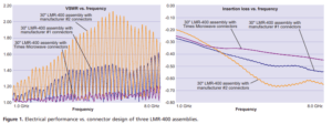
Figure 1 shows the electrical performance of three 50 Ω, flexible coaxial cable assemblies. The cable used in the demonstration is TMS LMR-400. The assemblies are the same length and terminated with the same interfaces. Each assembly is terminated with connectors from a different manufacturer, and each of the connectors was built and marketed for LMR cable.

Because each of the assemblies was built from the same lot of cable and terminated by the same person under the same conditions, the steadily increasing VSWR with frequency of the assemblies of manufacturer #1 and manufacturer #2 can be attributed to reflections because of impedance mismatches within the connectors.
These three curves demonstrate how the size and material transitions within a particular connector design may be compensated to perform well in increasingly higher frequencies. Looking at the insertion loss curves for the three assemblies, it can be seen that there is a wide discrepancy in the actual insertion loss of the assemblies. None of this variation is because of the cable. In comparing the two graphs, it can be seen that the points at which the assemblies exceed the theoretical linear loss curve correlate to points of high VSWR. This higher loss is due to the decreased efficiency of the transmission line (i.e., a higher percentage of the incident signal is being reflected at the connectors and not reaching the device to which the assembly is terminated.)
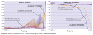
Figure 2 shows the electrical performance of three larger 50 m, flexible coaxial cable assemblies, TMS LMR-600. These are also the same length, terminated with the same interfaces and built with connectors supplied by the same manufacturers as in Figure 1.

The scale on the VSWR actually had to be altered because the reflections within the assemblies of manufacturer #1 and manufacturer #2 became so great with the increase in frequency. In examining the insertion loss curves, there is a frequency (roughly, 6.0 GHz) where these assemblies basically cease to function as a transmission line for all practical purposes.
Broadband Performance
It becomes increasingly difficult with connectors as with cable to design, build and maintain the tight process controls that are necessary to achieve a high level of performance over a broad frequency band. This is especially as the frequencies climb well beyond the 1.0 GHz level, such as in the 5.8 GHz ISM band. Though it is possible to optimize connectors to perform well in certain bands, it is rarely viable from an economic standpoint. Most connectors are rated for broadband performance to a specific maximum frequency. Unfortunately, most manufacturers of RF connectors have not been able to keep up with the improvements that would be necessary to obtain reasonably good performance at 3.7 or 5.8 GHz, never mind optimal performance. As little as three years ago, most data applications were operating below 1.0 GHz, and as recently as two years ago, most applications were operating below 2.0 GHz. It is these cellular and personal communications service (PCS) bands for which most connectors were designed. Someone working in these bands could basically pull any connector off of a shelf and it would be a pretty safe bet that the performance would at least be respectable. Most connector manufacturers were slow to understand that a connector that was sufficient in a PCS application at 2.0 GHz may not meet the requirements for a 2.4 GHz application in the ISM band. The proliferation of data applications in the ISM bands has placed certain demands on connector performance. These bands are unlicensed and, therefore, the Federal Communications Commission has placed power limitations on transmissions in these bands. The need to be assured that there is a sufficient transmit signal but at the same time make sure that the transmit power never exceeds the maximum allowable has, in many cases, created a demand for low-loss cable assemblies that are consistent and predictable in their performance. The nature of data transmission itself has also pushed systems to reduce noise levels to their absolute minimum. The best way to do this is to minimize the power levels of the system and, hence, the need for low-loss cable and, just as importantly, low-loss assemblies. As an added challenge, some of these systems are now operating in the 5.8 GHz band.
Conclusion
As the frequencies of new wireless applications continue to rise and the performance requirements become increasingly demanding, the connectors must be looked at closely. There are mechanical variables that affect overall electrical performance of the cable assembly or feeder run. Also, each connector has its own impedance characteristics similar to a fingerprint. These various designs are associated with different VSWR values at a given frequency and, in some cases, may have a significant impact on the overall insertion loss of an RF assembly.
Subscribe to our newsletter!
Interested in receiving email newsletters and other updates from Times? Subscribe now!
